|
|
|
|
Gears
|
|
|
|
Ring
|
|
Cover
|
|
|
Base
|
Total
|
Total cost of 100 parts
|
|
|
|
$920.84
|
|
|
|
$593.65
|
|
$854.12
|
|
|
$973.50
|
$3,397.11
|
Fix Costs
|
|
|
|
$868.62
|
|
|
|
$543.62
|
|
$678.12
|
|
|
$748.77
|
$2,839.13
|
Marginal Cost per 100
|
|
|
|
$52.22
|
|
|
|
$50.03
|
|
$176.00
|
|
|
$224.73
|
$557.98
|
Cost per part
|
|
|
|
$9.21
|
|
|
|
$5.94
|
|
$8.54
|
|
|
$9.74
|
$33.42
|
Marginal Cost per part
|
|
|
|
$0.52
|
|
|
|
$0.50
|
|
$1.76
|
|
|
$2.25
|
$5.03
|
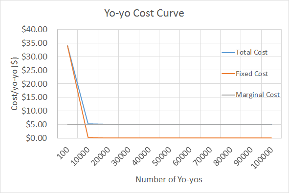
Cost analysis for prototyping versus manufacturing
The prototyping cost per unit part is relatively high. For the first 100 yoyos, the cost per part is $33.42. The is due to the following reasons:
- The hours invested working in CAD for the drawing of the parts and their assembly are labor intensive and expensive
- High labor costs. The initial stages involve the development of a concept and design each of the components making the yoyo.
- The molds of each part need to also be drawn with the appropriate dimensions to account for any shrinkage or press fits required.
- A large amount of hours is also invested in Mastercam, to be able to fabricate the molds.
- Prototyping requires the iteration of molds and the running of several trials to ensure the quality and matching assembly of the yoyo.
- The cost of labor per hour is one of the highest of the entire process (as seen in the cost chart) This results in a very high cost for the prototyping stage
The manufacturing cost per unit part is relatively low. The marginal cost per unit is only $5.03. In addition, the total cost per unit is only a few cents above this prices, as for a batch size of 100,000 parts, the fixed costs of $2,839.13 becomes almost negligible.
- The manufacturing costs of large batch sizes are mostly dominated by the material costs, the machines run time (costs of running the injection molding and thermoforming machine) and the overhead costs.
- The manufacturing costs is relatively low for a profit to be made
Assumptions on the cost estimation:
- No prototyping or modification of molds required after the first 100 parts (after finalizing the first batch of yoyos)
- The costs of the machinery and tools has not been included as part of the fixed cost (since it was not given as a variable in the available spreadsheet)
Limitations
Our team decided to make three injection-molded parts (the gears, ring, and base) and one thermoformed part (the clear cover) instead of two injection-molded parts and two thermoformed parts because there was only one thermoformed machine available in lab. We knew this would be the bottleneck since this machine is not quite as automatic as the injection molding machines. Thus, we saved time and decreased our cost.
Due to time limitations (fast approaching deadlines) our team had to make decisions quickly. Thus, we focused on one design instead of multiple like it is usually done in an ideation process.
We were limited to certain ejection pin diameter configurations. Therefore, we considered creating an outer ring concentric with our ring with runners to the ring so that we could eject our part properly. Fortunately, we were able to find an ejector pin diameter configuration and there was no need for this extra ring.
Changes for Mass Production
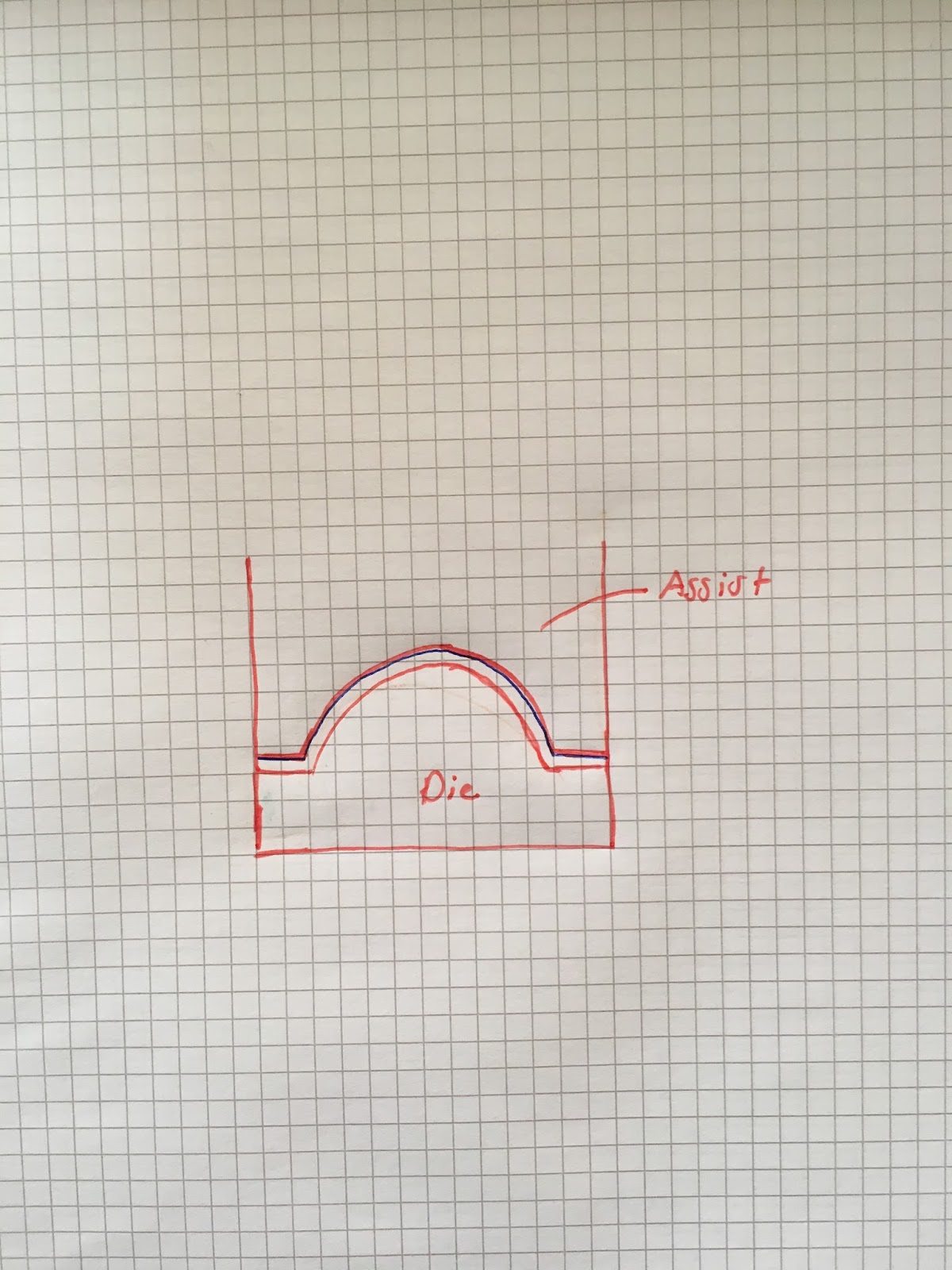
Cover:
We would add an assist to our thermoformed part for mass production. During our production run for 100 runs, the covers were produced with small deformations on its apex due to air. This was difficult to address, especially due to time constraints. The assist would therefore help eliminate these deformations.
We observed that the ring displayed sink marks characteristic of shrinkage at the middle section of the thickest cross section. We would also consider decreasing the thickness of the ring to minimize the amount of shrinkage.
Gears:
The use very little material and have a low cooling time which is ideal for mass production. The limitations that we encountered was that the gears, due to shape and mold design, often stuck to the cavity. In mass production this could be a large problem because it would require human intervention. The problem could be mitigated by creating a taper along the gears holes. Another consideration is during assembly. Due to small size and shape, assembling the gears on a peg becomes a problem of specific placement. The taper along the holes could also help with less precision during placement for gear assembly.
Base:
We had limited range of ejector pin placement, where in a factory we could generate our own ejector pin framework. This significantly impacted our design, forcing us to re-machine our molds to comply with existing framework. Besides the ejector pin constraints, the design gave no issues in low-scale manufacturing.